The Calcutron-33 Decimal-Based Computer
An introduction to microprocessors and assembly programming for beginners
The Calcutron-33 computer is a thought experiment: What if we could build a computer that worked on decimal numbers rather than binary numbers? In our imagination anything is possible and through code we can simulate just about anything. In fact, I have created a simulator for the Calcutron-33 computer,which you can download. The simulator allows you to write programs for this imaginary computer and run them.
The purpose of the Calcutron-33 computer is to serve as a stepping-stone towards learning how to write RISC-V and Arm assembly code. Ultimately, that is what you want as there are actual computers built around the RISC-V and Arm microprocessor architectures, while no Calcutron-33 based computers exist in the real world.
In this story, I will cover the following:
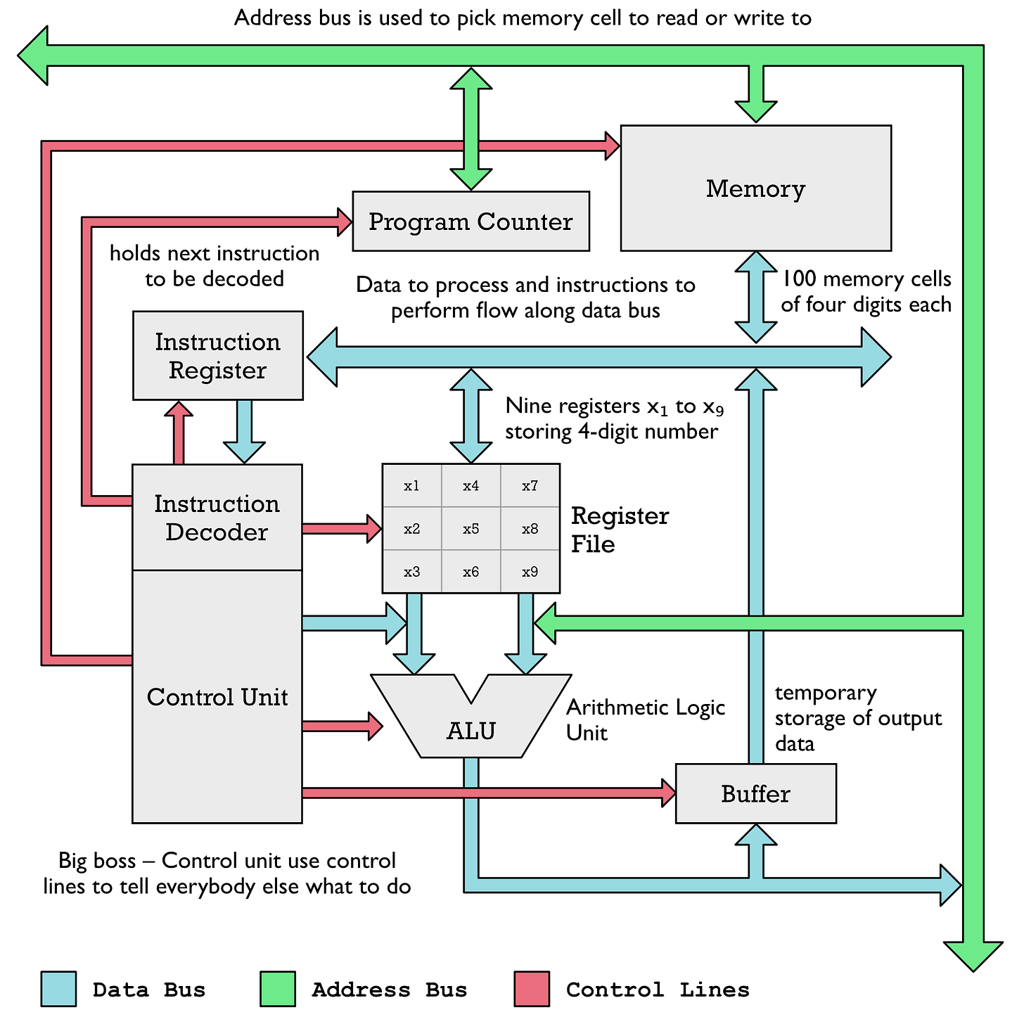
The architecture of a microprocessor – What functional units comprise a microprocessor, and how do they interact with each other?
Program execution – How does a microprocessor run a computer program loaded into memory?
Instruction-set – The operations a microprocessor can perform
Assembly code – How to write and run programs
When I cover this material, I will intentionally blur the lines between a computer and a microprocessor. Normally, a microprocessor doesn't contain main memory, but since they contain fast-memory called cache, we can kind of pretend that they do. Historically, there was no clear separation between the two until we got microprocessors packaged into separate silicon chips. Now, we have come full circle with systems on a chip (SoC) such as Apple's M1 chip where a package contains a whole computer system.
The Architecture of a Microprocessor
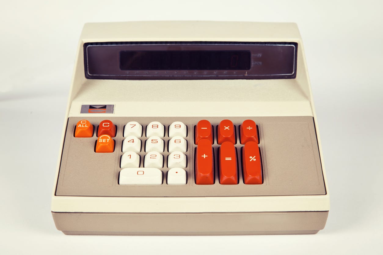
A microprocessor is made up of several functional units. One of the more important ones is called the Arithmetic Logic Unit (ALU). It works much like a calculator. It can perform the following basic operations:
Add and subtract two numbers
Shift a number to the left or right
Incidentally these same operations were covered in my previous article: From Arithmometer to Microprocessors. Here is a quick refresh of what a shift operation is about. Shifting involves adding or removing digits to a number. It is a fast and simple operation to scale up or down the value of a number by multiples of ten (when working with a decimal computer).
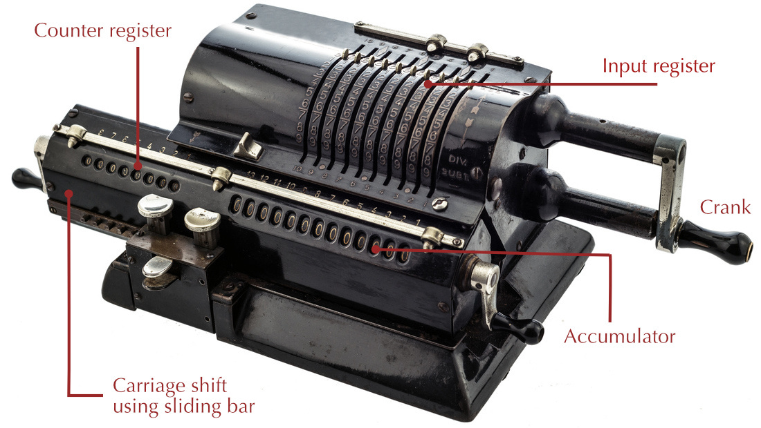
As I have discussed in earlier articles, the Arithmometer, was a mechanical calculator which performed these exact same operations.
The ALU serves the same purpose as an arithmometer. Historically, an arithmometer only had an input, accumulator and counter register. A microprocessor in contrast tends to have numerous registers. The gray boxes labeled r1, r2 and r3 in the illustration below represent registers. A register is a memory cell that can hold a number. Normal computer memory is just a collection of registers. However, in casual speech, when somebody says register, they typically mean a memory location inside the microprocessor used to perform a variety of operations.

On the Calcutron-33, every register can hold a 4-digit decimal number. A modern computer contains 64-bit microprocessors, which means each general purpose register can hold a 64-digit binary number. A binary number digit is called a bit, which is why we talk about 64-bit processors rather than 64-digit processors.
A computer adds functionality around the ALU to essentially create a programmable calculator. A program in memory tells what operations the ALU should perform and which registers are involved in the operation.
The Register File
In a real microprocessor, you have a whole block of memory called the register fileto hold all the registers which can be used as inputs and outputs to the ALU.
NOTE: When I first heard the term register file, it confused me because I was thinking about files in the filesystem, but it has nothing to do with that. The terminology is unfortunate but widely used when discussing microprocessors, so get used to it.
The Calcutron-33 register file is divided into nine registers named x1, x2, ..., x9. Modern RISC processors such as the RISC-V and 64-bit Arm processor have 32 registers to play with.

The register file has several address ports, so you can select two output registers and one input register at the same time when performing an operation. Not shown in the diagram is register x0. It doesn't have a storage location because you can never store anything in it. Instead, it always has the value zero. Later I will explain why that is such a clever design choice. In other words, you can technically refer to ten different registers, but only nine of them are capable of storing data.
Anatomy of an Instruction
You can tell the ALU to add two numbers using the instruction ADD x4, x2, x1. This instruction will add the numbers located in register x2 and x1 and store the result of the addition in register x4. This instruction follows a common pattern for most RISC processors, not just Calcutron-33.
We can break any instruction into several parts: the mnemonic ADD which tells the ALU to perform an addition. x4, x2, and x1 are what we call the operands of the instruction. The operands are the inputs and outputs to an instruction.
When describing how this instruction works, we would write something like: x4 ← x2 + x1. It helps clarify what registers are combined and where the results are stored. This is useful to know, as different assemblers follow different conventions. Calcutron-33 follows the same convention as RISC-V, Arm and x86 which place the destination register first.
The first microprocessor I learned to write code for, Motorola 68000 (often called 68k), placed the destination register at the end. For instance, the 68k instruction ADD.B d2,d4 could be described as doing the operation d2 + d4 → d4.
Assembly code to machine code
I have just described the format of an assembly code instruction. A microprocessor doesn't actually run assembly code. A microprocessor only operates on numbers. Thus, a program called an assembler is used to convert assembly code to machine code. For an actual computer, the machine code would be binary numbers such as 00101011 and 11101001 (only ones and zeros). However, Calcutron operates on decimal numbers, so the assembly code instruction ADD x4, x2, x1 is translated to the number 1421. The last three digits, 421, represent the operands to the instruction. The first digit (1) represents the opcode. Every mnemonic translates to an opcode. The opcode tells the processor what operation to perform. If you had written 3421 instead, then the processor would have performed a subtraction instead because the number 3 is the opcode for subtraction. Calcutron-33 assembly express this instruction as SUB x4, x2, x1.
For early computers, there was no assembler program. Instead, an actual human being was the assembler. A software developer would write their assembly program on a sheet of paper. Next, the developer would translate by hand the assembly code to machine code. That means you needed an overview of the whole instruction-set, along with information about how each instruction is encoded. Instruction encoding can be very complex. I recall a fun anecdote about one of the great minds of computer science, John von Neumann, which shows that even the greatest minds can be stubbornly narrow-minded:
One of von Neumann's students at Princeton recalled that graduate students were being used to hand assemble programs into binary for their early machine. This student took time out to build an assembler, but when von Neumann found out about it he was very angry, saying that it was a waste of a valuable scientific computing instrument to use it to do clerical work.
Fortunately, Calcutron-33 has a simple instruction encoding: Every instruction is four digits long. The first digit is always the opcode, and the remaining 3 digits are the operands.
Not every instruction has three operands. For some instructions, an operand requires two digits. One example is the Add Immediate, ADDI instruction. To add the number 42 to register x5 you would write ADDI x5, 42. This instruction would be encoded as 2542. The immediate value 42 required two digits in the instruction to be encoded. Registers only require one digit because there are only 9 registers.

Data and Address Buses
The gray blocks in the Calcutron-33 architecture diagrams perform different operations, but we require a way to be able to transmit data between the functional units (gray blocks). That is what the colorful arrows are for. They are called buses. In real computers, these are electric wires or copper traces on a printed circuit board connecting functional units made up of transistors. In modern computers, most of the buses exist inside a silicon die. Each colored bus serves a different purpose:
Data bus – Moves around instructions and data instructions operate on
Address bus – Used to specify an address in memory to fetch data from
Control bus – To toggle on and off inputs and outputs from different functional units
To explain the purpose of different buses, I like to use an analogy with gas pipes with valves. You can think of a computer system (or microprocessor) as various gas tanks connected by a complex web of pipes. At any given time, gas only flows from one tank to another. To avoid that gas flows to multiple places, we must open and shut the correct valves.
You will notice in the architecture diagrams that the colored pipes connect to multiple functional units. Yet, we only want data to flow between two units at any given time. In the pipes analogy, you can think of the red control lines as being connected to electro-magnets on the valves to open and shut them.
All the red control lines are controlled by the control unit, which is a bossing around the whole microprocessor, telling it what data is allowed to flow where. For instance, if the control unit wants to send a number from memory to a register, it has to close the values to all functional units except the output value on the memory block and the input valve on the register block.

Memory contains numerous memory cells. In the Calcutron-33 computer, every memory cell contains a 4-digit decimal number. A real computer would contain a byte value (8-bit number) at each address.
To know which number to send to the register file we need to specify the address of the byte to send. Calcutron-33 contains 100 memory cells numbered from 0 to 99. The first memory cell is given address 00. The second memory cell is given address 01 and so on. As mentioned earlier, you also provide the register file with addresses to pick output and input registers for each operation.
How Does a Microprocessor Run a Program?
A microprocessor runs a program by fetching one instruction after the other in turn. The program counter (PC) decides which instruction to fetch next. It is incremented by one each time an instruction is executed, except when a branch or jump instruction is executed. A branch or jump instruction will modify the program counter and thus effectively jumping to another location in the program being executed.
Fetched instructions are placed in the instruction register, where they get decoded. Based on the decoding of an instruction, the control unit (CU) orchestrate and organize the activity in the rest of the processor. I have written an in-depth article about how this works:
The Calcutron-33 Instruction-Set
Once you know how a basic instruction is executed in a CPU, the next step is to get an overview over the instructions your microprocessor understands. The Calcutron-33 microprocessor understands 10 basic instructions. You will, however, see 12 extra instructions listed, the so called pseudo-instructions. These are not "real" instructions, but get translated to one of the 10 basic instruction supported by the processor.
Writing Assembly Code
When you got an overview of how assembly instructions work and the instruction-set (ISA) that exists for Calcutron-33 you can experiment with writing your own code after downloading the latest release of the Calcutron-33 assembler, simulators, disassembler, and debugger. All these tools are bundled into one command called cutron. This next article explores how to use all the different tools to solve some simple programming challenges for beginners to assembly programming.
If you have worked your way through these examples you have a good foundation to begin learning about other microprocessors such as RISC-V, Arm, x86, Motorola 68k, AVR and others.


https://archive.org/details/bitsavers_burroughsBryDumpSep79_5553606/mode/2up
https://www.jaapsch.net/mechcalc/burroughs_books.htm
https://www.picklesnet.com/burroughs/documents/Burroughs%20B80%20-%20A%20Bargain%20System.pdf
I can't find the instruction set. Not surprising, I doubt Burroughs really wanted to publish it. The B80/90 vanished without trace or descendants in 1981, when Cumbernauld was shut down.
The Burroughs B-80 computer from 1978 was a silicon realization of a mechanical calculator, complete with 20-digit decimal accumulator. In Cumbernauld, Scotland they were still making the mechanical marvel on the main factory floor. When I arrived to work on the chip my desk contained a service manual for the calculator, which contained roughly 10,000 parts which unfolded in layers to allow service access. Just amazing, a bit like watchmaking scaled up to a 30 kg electric typewriter.
It was the most bizarre instruction set I ever worked on, it made a Z-80 look like a marvel of symmetry. Every register was special purpose, and if you could operate from A to B you could be sure the operation from B to A did not exist. It had a COBOL compiler and an OS, and was widely used for data entry systems in banks since it was (for the time) highly integrated into 2 chips and fit in a desk with the CPU about the size of the drawers you would have on one side. My work was to add transparent memory swapping so the DRAM could go beyond 64kB in the B-90, its successor. The rise of the PC wiped out that business, they closed the plant in 1981.