
Grokking RISC-V Vector Processing
A friendly introduction to the core concepts in the RISC-V “V” Vector Extension, version 1.0


While the basic idea of vector processing is simple, the details can get complex. The purpose of this story is to explain the fundamental idea of vector processing and how that has been implemented in the RISC-V instruction-set architecture. I call this a “friendly” introduction but I must warn you that this stuff is still hard to grasp.
Vector processing is based on the idea of executing a single instruction on multiple elements of data in parallel. We refer to this concept as single-instruction multiple-data (SIMD) usually contrasted with single-instruction single-data (SISD).

However when developers talk about SIMD today they usually refer to packed-SIMD instruction sets such as MMX, SSE and Neon. These types of SIMD instruction sets operate on fixed length vectors (length in bits is known). Each instruction is tailored to a particular number of elements and a known vector length. The RISC-V P extension is an example of such SIMD instructions. Here is a simple example:
# RISC-V Assembly: Add two 16-bit values.

LW    x2, 12(x0)   # x2 ← memory[x0 + 12]
LW    x3, 16(x0)   # x3 ← memory[x0 + 16]
ADD16 x4, x2, x3   # packed-SIMD instruction
SW    x4, 20(x0)   # x4 → memory[x0 + 20]
For packed-SIMD instructions such as ADD8, ADD16 and ADD32 the bit length of each element is given as a number suffix. For instance ADD8 adds 8-bit elements. ADD16 adds 16-bit elements. How many elements? That depends on the register size. For a 64-bit RISC-V processor ADD16 would add four elements in parallel, while a 32-bit RISC-V processor would add two elements in parallel. This approach is somewhat limiting as the number of elements you can process in parallel is constrained by the word size of the processor.
The size of a word is reflected in many aspects of a computer’s structure and operation; the majority of the registers in a processor are usually word-sized and the largest datum that can be transferred to and from the working memory in a single operation is a word in many (not all) architectures. — Wikipedia
With vector processing, enabled by the RISC-V V extension, we get a far more flexible system, because vector registers can be of any length, regardless of word size. If a CPU implements the V extension it must support the following:
32 vector registers named v0, v1, …, v31.
Each vector register is at least 128-bits long.
Allow developers to set the size of each vector element to 8, 16, 32 or 64 bits.
Let me clarify with some concrete examples from SiFive (RISC-V CPU designing company): The P270 core from SiFive has vector registers which are 256-bits long, while their X280 core has 512-bits long vector registers. Thus as single vector instruction can process a whopping 64 8-bit values on an X280 core. The P270 and X280 can run exactly the same machine code despite using vector registers of different length.
Some of the newest SIMD instruction-set extensions out in the market do support 512-bit vector registers. However RISC-V has added a unique twist called register grouping. It allows you to group up to 8 vector registers to form a “virtual” mega register. Through grouping the X280 allows you to work with vector registers which are a crazy 4096-bits long. That means you could compare two strings with 512 ASCII characters by just issuing one vector instruction (excluding the setup code).
Control Status Registers (CSR) and vtype
Working with vectors requires you to configure the width of each element and the number of registers you want to group before you start. This is done by setting a register called vtype in the control status registers CSR. Don't mistake these status registers with the 32 general purpose registers x0, x1 ..., x31 on the RISC-V processor. There are 4096 CSRregisters on the processor but these cannot be used for arithmetic and logic operations.
You can only read from the CSR registers to get info about the capabilities of the CPU your program is running on. In addition you can write to the the CSR registers to alter the behavior of the CPU. For instance if you want to figure out what instruction extensions are supported on your CPU, you can read that information from a CSR register.
The exact location of each CSR register is not directly available to you. Instructions that set e.g. the vtype register doesn't tell you where it is located. For instance this instruction will set the vtype register.
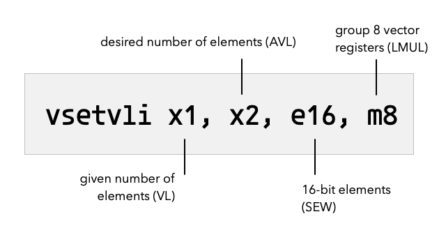
Before I can explain properly what this instruction does, I need to clarify a few important RISC-V vector processing concepts.
The theoretical max number of elements a RISC-V processor can process in parallel with a vector instruction is called VLMAX. Your processor will calculate VLMAX based on the size (in bits) of your vector registers, how large you want each element to be (in bits).However, the number of elements you actually want to process AVL might be more or less than VLMAX.
Thus we need to introduce a third concept VL, which is the number of elements you actually end up processing with each vector instruction after the vtype register has been configured with the vsetvli instruction. The following equation clarifies the relationship between VLMAX, AVL and VL:
VL = min(AVL, VLMAX)In out earlier example we provided the desired number of elements, AVL using the x2 register, while the actual number of elements the CPU can process, VL, gets computed and stored in the x1 register as a result of executing the vsetvliinstruction.
x1 ← min(x2, VLMAX)These vector concepts can be confusing because there are many closely related terms to keep apart. So let us cover each one in more detail to give the full picture.
Vector Register Group Multiplier (LMUL)
In the vtype register (remember part of the CSR registers) there is a setting for how many registers are grouped. This setting is called LMUL. The graphics below helps explain how the setting works.

Notice that LMUL allows fractions which means instead of grouping registers you can pick just a fraction of a register. When we group register we refer to the group by the name of the first register in that group.
In my graphical illustration only eight registers are shown. On a RISC-V processor there are of course a lot more registers (32 vector registers), but I drew fewer to make the concept of grouping more clear.
Even if you have grouped multiple registers, that doesn’t mean you necessarily use the max number of elements. You may have set the the vector length VL (number of elements) to lower than the max number of elements (VLMAX).
 is not necessarily the same as max number of elements (VLMAX)")
Here is a description of what each blue column illustrates:
No grouping of vector registers but using the full register.
Grouped two register but the whole group is not used.
Grouped three registers. Again not all elements used (VL < VLMAX)
Fractional vector register picked with LMUL, but we are using the whole fraction in vector calculations.
Set Element Width (SEW)
Another important setting in the vtype register is the SEW setting which specifies the desired number of bits for each element in the vector register. VLEN is the total number of bits for a vector register. It is hardwired on each particular microprocessor and not something you can programmatically change. Together SEW and VLEN allows you to calculate the max number of elements which one vector register can contain.

Calculating Max Number of Elements (VLMAX)
With LMUL and SEW set we can calculate the max number of elements which can be processed by a vector instruction:
VLMAX = (LMUL × VLEN) / SEWOf course you don’t perform this calculation in your code. The hardware does that for you behind the scenes. Thus the way we figure out the number of elements, VL which we will be using can then be expressed as:
VL = min(AVL, VLMAX)
VL = min(AVL, (LMUL × VLEN) / SEW))
The vsetvli will perform this calculation for us and store VL in the destination register (a general purpose register such as x1 or x4).
How an Array of Data is Processed
When processing an array of data you might have a huge number of elements. There could be thousands of elements and there is no way your processor can process all of them at the same time. Thus your desired vector length, AVL will at the start be much longer than you can process in one go.
Instead the number of elements you get to process VL, will be limited by VLMAX (calculated from LMUL and SEW and VLEN). The solution is to process our array by sliding a "window" across it of VL length which process elements as shown in the illustration below.

As you process data in the array you desired vector length, AVL, will shrink. But why? Because every time you have processed a chunk of the data array, there are fewer elements left to process.
At the very end you will be left with a desired vector length VL, which is shorter than VLMAX. In practice the way you setup processing of an array is by running a loop where you repeatedly call vsetvli to adjust the vector length to fit with the number of elements left. The desired vector length is always equal to the number of elements left to process.
Every time you repeat the loop you reduce the number of elements left to process. Thus you attempt to set the vector length to that number of elements. Once the number of elements left to process is zero, you know that you are done processing all the data.
Code Examples
To better understand how all these pieces work in practice we will look at some code examples.
Scale Vector and Add To Another Vector (SAXPY) Example
A classic function used to show all sorts of vector processing is the saxpy function popularized by the BLAS linear algebra library. Give two input arrays xs and ys it performs the following calculation for every element in the input arrays.
ys[i] = a * xs[i] + ys[i];This operation can be implemented as C function as follows:
// Single-Precision a × X Plus Y,
void
saxpy(size_t n, float a, float *xs, float *ys) {
    for (size_t i=0; i<n; i++)
        ys[i] = a * xs[i] + ys[i];
}
Let us look at a RISC-V assembly code implementation of this function. Function arguments are passed in general purpose integer registers such as x1, x2, ... x31, however to make it easier to remember which registers are used the RISC-V specification defines useful aliases:
Function arguments —
a0,a1, ...,a7Temporary registers —
t0,t1, ...,t6
The same applies to floating point registers f0, f1, ..., f31. We also got aliases:
Function arguments —
fa0,fa1, ...,fa7
So the function arguments map to registers as follows:
nmaps toa0amaps tofa0, because it is a floating point numberxsmaps toa1, because it is the address to an arrayysmaps toa2, because it is the address to an array
We use a0 to store elements left to process, while t0 contain the number of elements actually processed on each iteration.
saxpy:
    # t0 ← min(a0, (VLEN × 8) / 32)
    vsetvli t0, a0, e32, m8, ta, ma

    vle32.v v0, (a1)    # v0 ← mem[a1:a1+t0]

    sub a0, a0, t0      # calc xs elements left to read
    slli t0, t0, 2      # t0 << 2 (each element is 4 bytes)
    add a1, a1, t0      # point a1 to next xs batch to read

    vle32.v v8, (a2)    # v8 ← mem[a2:a2+t0]
    vfmacc.vf v8, fa0, v0  # v8 ← fa0 × v0 + v8

    vse32.v v8, (a2)    # store batch of results at a2
    add a2, a2, t0      # point a2 to next ys batch to read
    bnez a0, saxpy      # goto saxpy if a0 ≠ 0
    ret
Notice in the example above how we use vector register v0 and v8 when performing our scaling and addition with the vfmacc instruction. Why not v0 and v1 instead? Notice the use of the m8 argument when calling vsetvli. m8 says that we want to group eight registers into one big virtual register. Thus v0, v1, ..., v7 are treated as one big vector register.
Vector Addition Example
The most basic and simple function can be useful as a reference. This code example merely adds elements in arrays xsand ys and stores the result in the zs array.
void vadd(size_t n, int *xs, const int *ys, int *zs) {
    for (size_t i=0; i<n; i++) {
        zs[i] = xs[i] + ys[i];
    }
}
Turned into RISC-V assembly code we get:
vadd:
    # configure to use 32-bit elements
    vsetvli t0, a0, e32

    vle32.v v0, (a1)     # read batch of elements from xs
    sub a0, a0, t0       # decrement by elements done
    slli t0, t0, 2       # no. elements to bytes offset
    add a1, a1, t0       # bump *xs pointer to next batch

    vle32.v v1, (a2)     # read batch of elements from ys
    add a2, a2, t0       # bump *ys pointer to next batch
    vadd.vv v2, v0, v1   # add xs and ys batch
    vse32.v v2, (a3)     # store result at *zs
    add a3, a3, t0       # bump *zs pointer to next batch
    bnez a0, vadd        # is n = 0, or more elements left?
    ret
In this example we didn’t grouping which is why we are using vector registers v0, v1 and v2 as the operands to the vadd instruction.
Memory Copy Example
The next example is to copy from a src address n element to a destination address dest.
